At Last!. I have started on my car ;-) PART 2

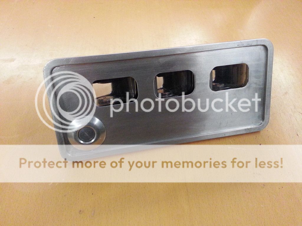
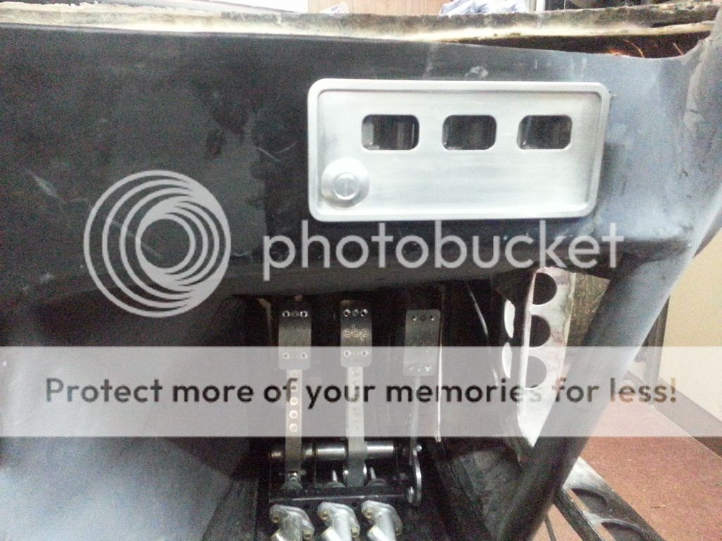
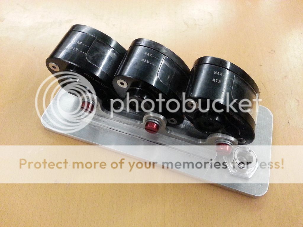
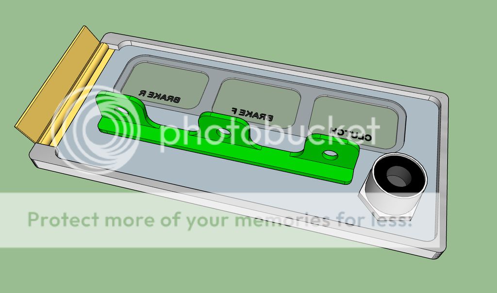
Fluid reservoir holder fabricated. Just needs a hinge, a little more sanding, perspex windows and cross hatching on the front (when new engraving cutter arrive) to disguise the iffy machining. It bares a vague resemblance to the SketchUp drawing The screws are a tad long (hence the extra washers) but this will be rectified (As Colin Chapman was heard to say many times, "Never take a washer for a free ride"). This will be located in the dash, so it can be seen by driver without contravening FIA and MSA regs.


http://s294.photobucket.com/user/el...lder fabricated 050317 1_zpsz3ciwsfd.jpg.html
 
Update time.

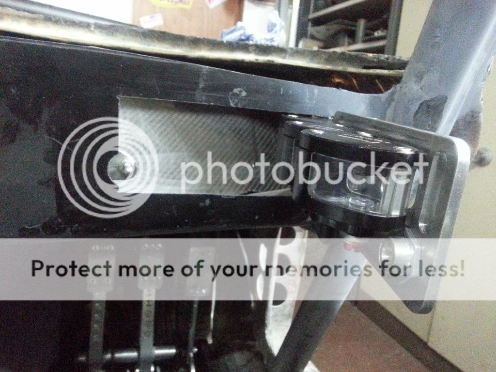
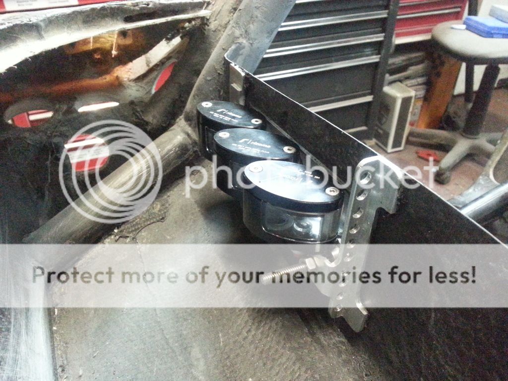
Fluid reservoirs fitted.


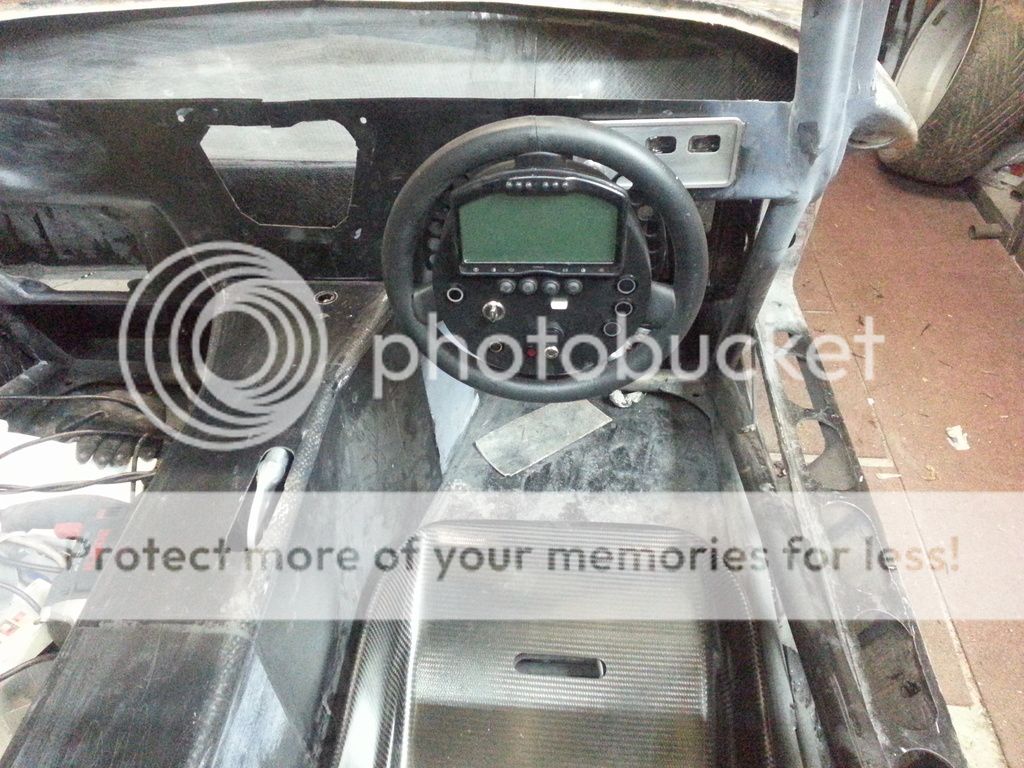
Then on to my personal Elephant in the room, the steering column. I thought that this was going to be a bit of a mission, requiring two UJs with accompaning support and bearings. However, it turned out to be simpler than I feared. Only required one helicopter joint and a simple U clamp secured to the horisontal roll cage tube. A friend brought round a 32mm U clamp with a flat curved part so I didn't even need to make a spreader to stop clamp from squashing the aluminium column surround. I now just need to make a curved support for the bottom of the column surround and a bracket to weld to the cage.


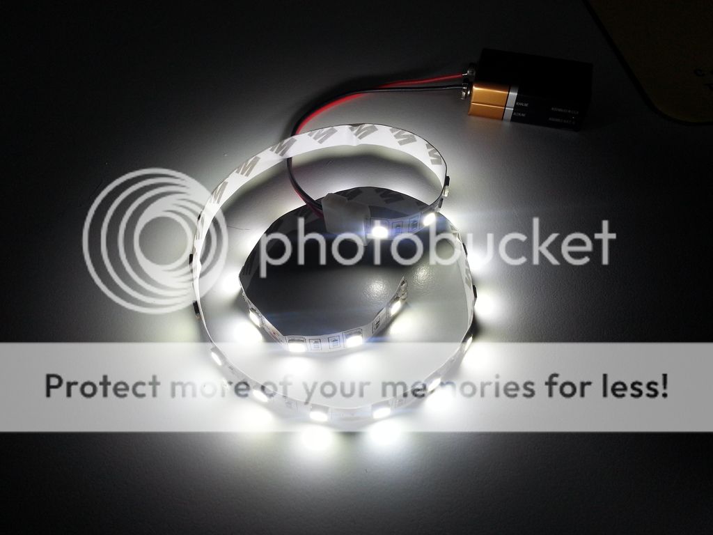
Just in case I have to back light the fluid reservoirs. 62p from China including P&P
1f642.png


Finally, after a lot of head scratching and numerous emails to the distributor, I have a working reservoir holder door latch.

 
Having learnt how to fit the latches, the boot was a breeze. What do you think about the panel gap? What gap? I hear you ask. Precisely, I reply
1f642.png
Not finished, but pretty tight methinks. I like it anyway.


Handbrake gaiter trial fit after modification. Just sitting in place so not precisely lined up with console. Brush is from a domestic draught excluder.

 
Now, what does a weight obsessed anal retentive do when he has a few minutes spare and doesn't want to start something too complicated? He does some weight reduction of course.

To that end I decided to have a go at the steering column clamp. This clamp allows column length adjustment as well as allowing it to collapse in the event of a front end shunt. The column now has a kink in it so it is probably not now required but I an keeping it both for the adjustment and extra safety.

However, it is bloody heavy at 174gms! A quick session on the mill, shortening the grub screw and replacing bolts with titanium versions resulted in a reduction of 84gms, almost half
1f642.png
The clamping plate fits properly when on the right way round.


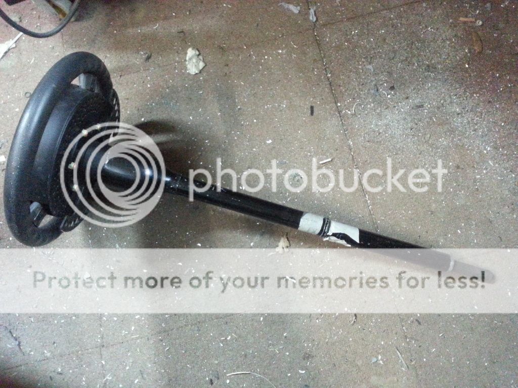
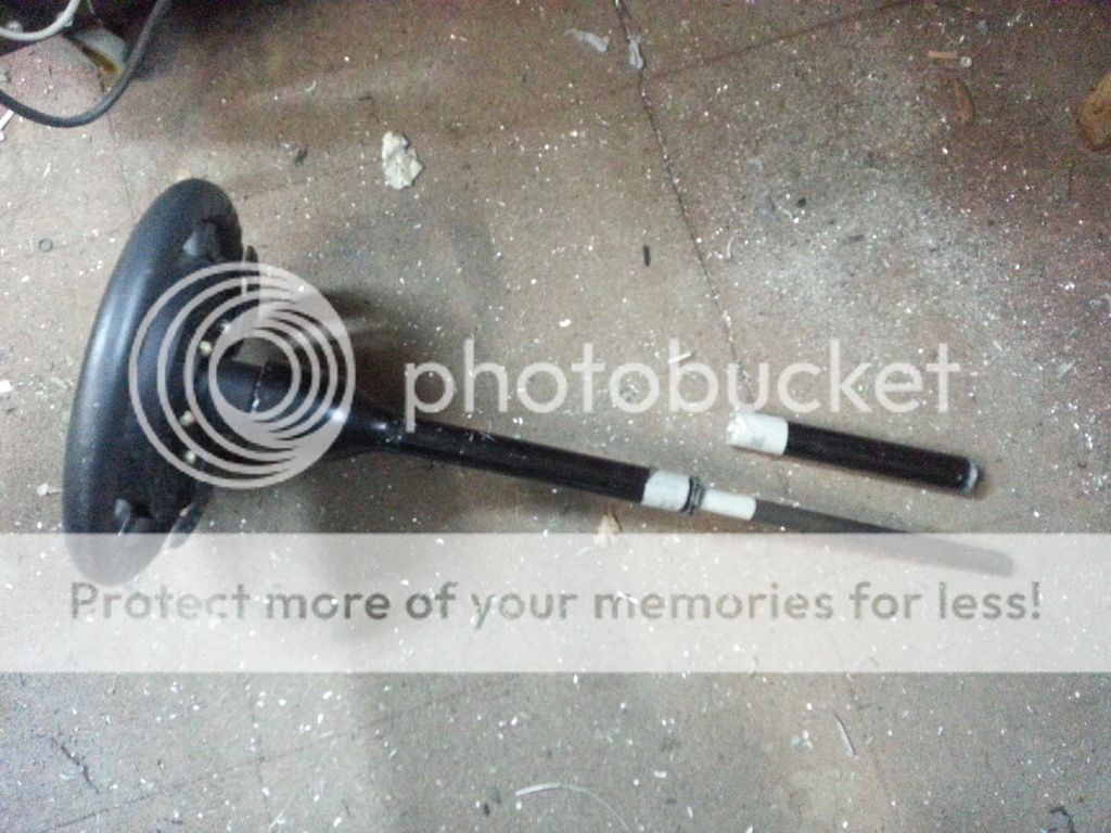
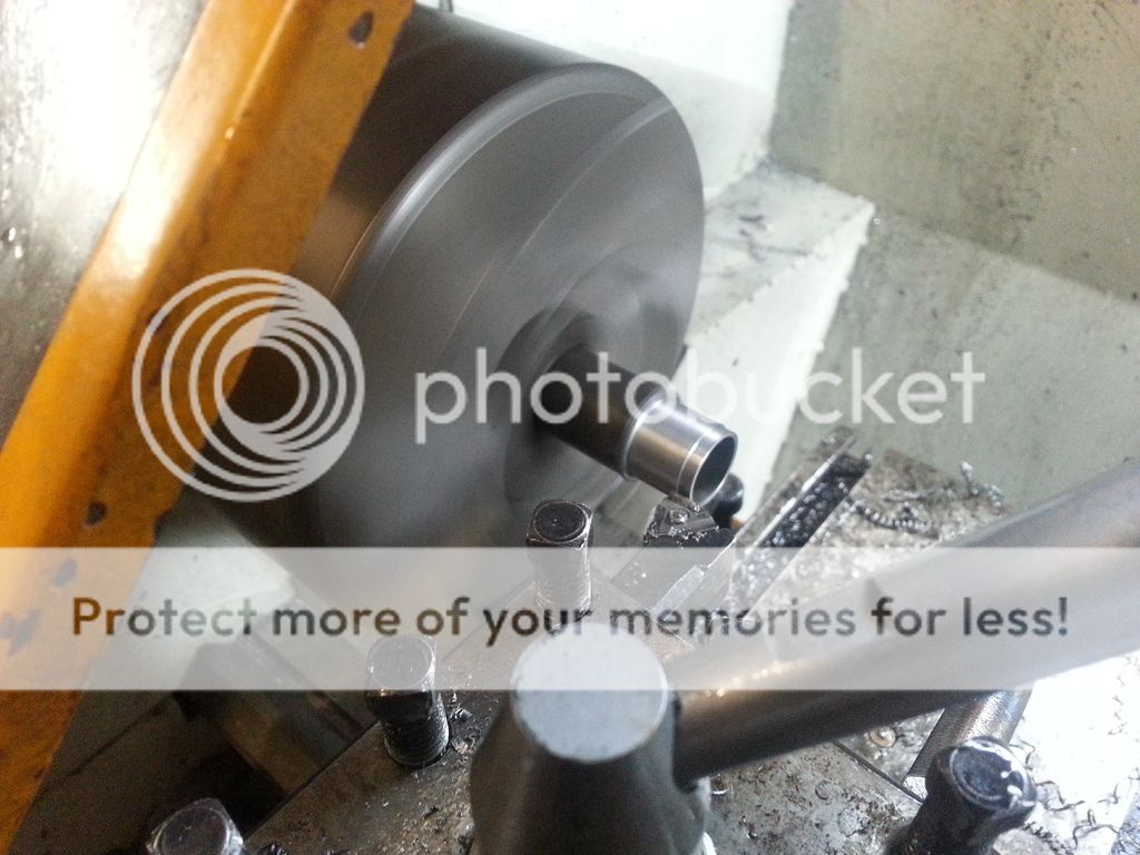
Titanium steering column coming together. The original splined ends in the rack knuckle and quick release steering wheel hub have been retained for simplicity. The joints between steel and titanium will be strengthened with titanium sleeves. You can just see the clamp I modified earlier.


Needed fixings to hold dash panel in place. They have to be hand turnable as access will be limited (ie through glove box) so decided to make them.


Thanks for the update, wondered if you were ok. It's the small jobs that count, too many people skimp on the details IMO.

What's your plan over the next few months?
 
I'm fine Waynne, but thanks for your concern.

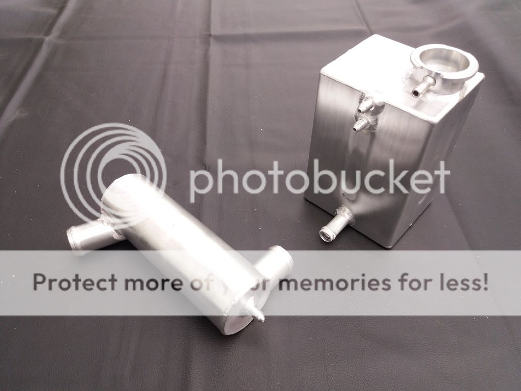
Water header tank and swirl pot have been made and trial fitted.


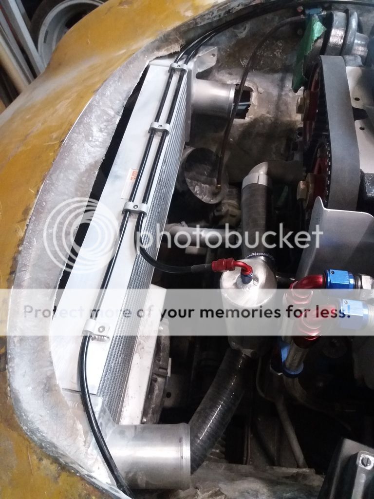
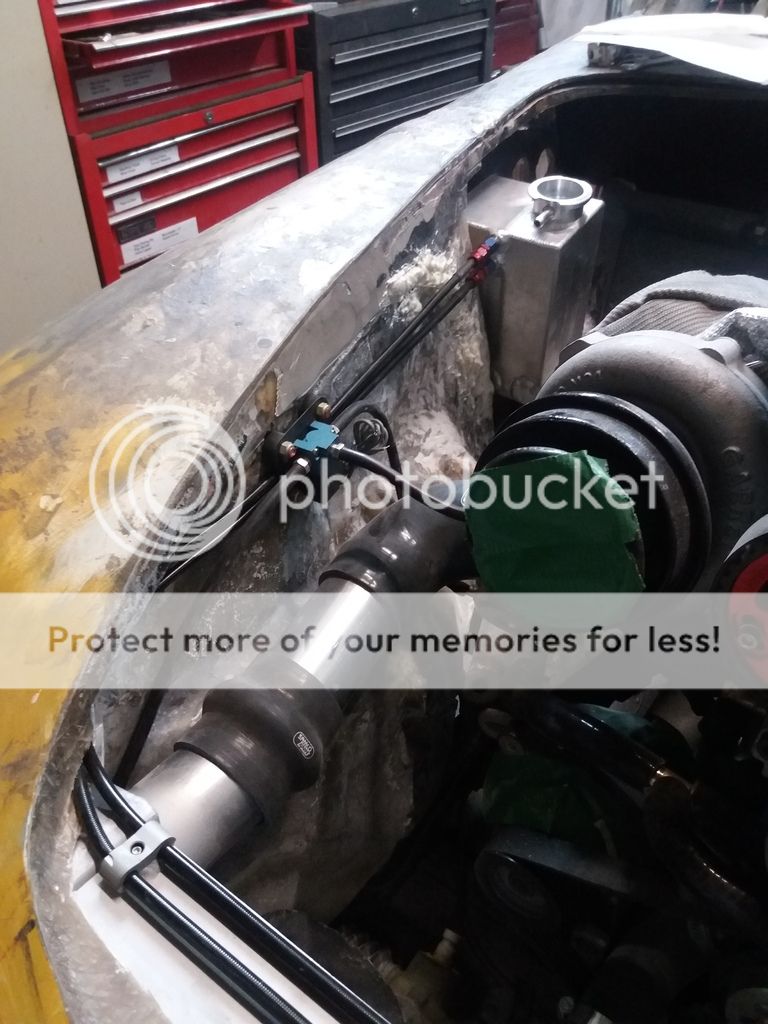
Breather pipes from radiator and swirl pot made and fitted. Electronic boost controller fitted and tubes sorted.


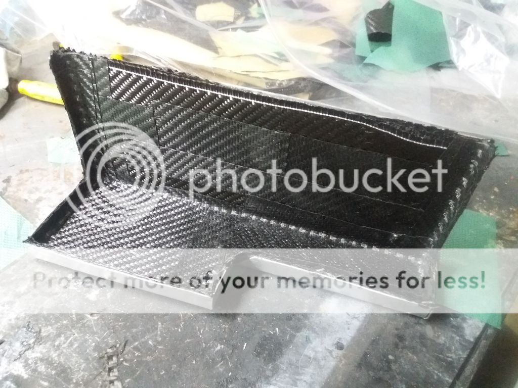
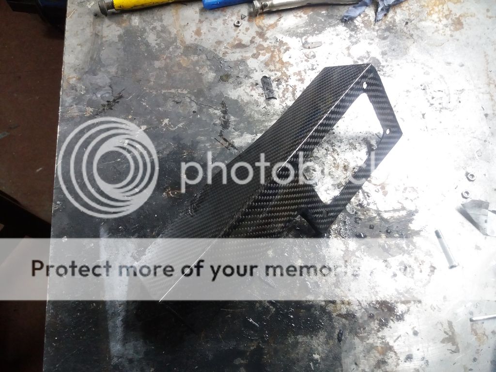
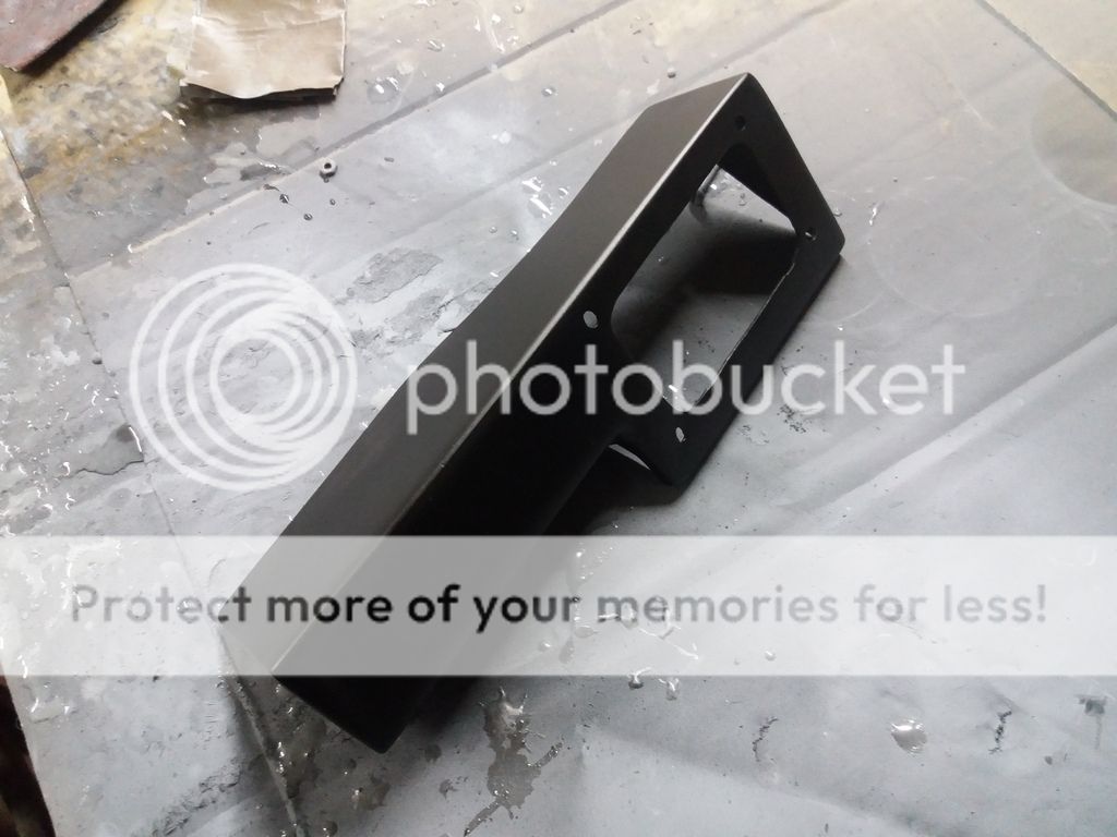
Support bracket for coil pack and oil, fuel and boost pressure sensors made in prepreg carbon and painted.


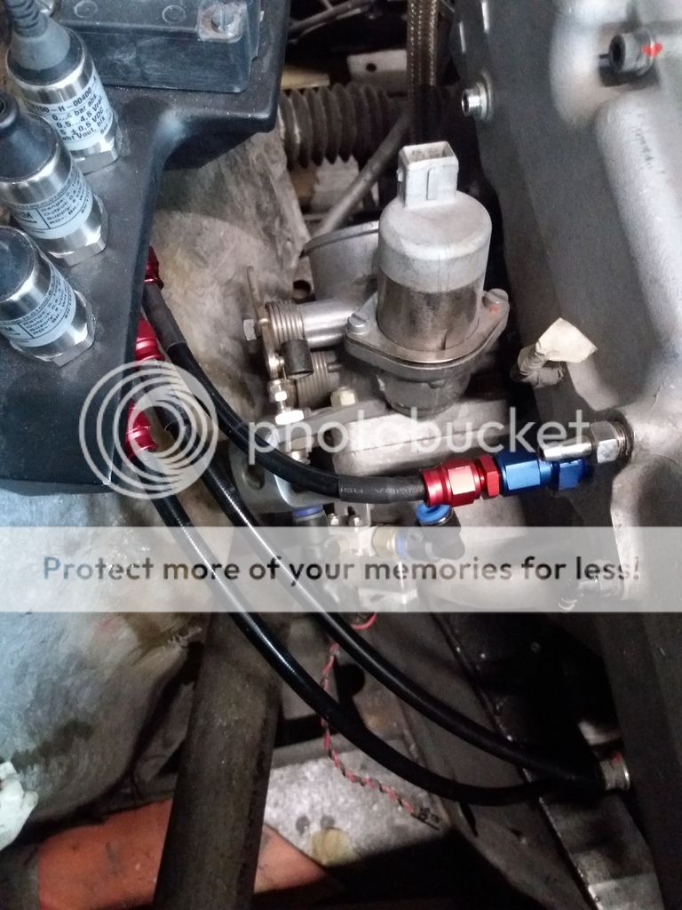
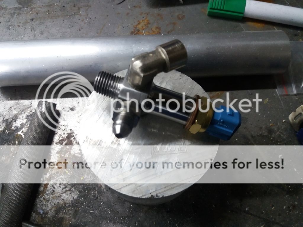
Made an adaptor to house turbo oil feed along with oil pressure and temp sensor pipes.

 
Your actually making most of these components yourself? That is so cool. Is this to save money or because you won't get the spec/size you want by buying it?
 
Your actually making most of these components yourself? That is so cool. Is this to save money or because you won't get the spec/size you want by buying it?

Because what I am doing hasn't been done before (as far as I can make out) there isn't any stuff made for my car. If I can buy stuff off the shelf I do but this is rare (can't think of anything offhand, apart from instruments, sensors, reservoirs, etc). If I could have bought the adaptor for the sensor pipes I would have done rather than make one. A lot of swirl pots and header tanks are not made correctly or are of the wrong size for my application.

Making stuff exactly how you want it rather than having to compromise is fun and satisfying, and also cheaper :)
 
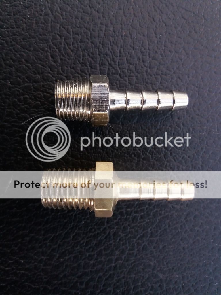
Needed a barbed connector with a longer threaded section and not tapered, so I made one.


Then, of course, I realised that I didn't have any M10 x .125 nuts. Back to the lathe :)

 
Is there no end to this mans talents |B

IF this project ever gets finished he won't know what to do with the sudden arrival of all the spare time that he hasn't had for so many years :eek: :lol:
 
Is there no end to this mans talents |B

IF this project ever gets finished he won't know what to do with the sudden arrival of all the spare time that he hasn't had for so many years :eek: :lol:

Anyone with a lathe can make these. However, I was quite chuffed with the finished product.

You know that a project car is never finished :)
 
Photobucket are now charging $399 a year to allow linking photos to websites! No thanks.

I can upload photos to sites such as Retrorides, LotusElan.net and Facebook directly from my PC, so why not here?

Other free options?
 
Last edited:
I have been working on the electonic components layout and I think that I am almost there. Anyway, I have booked an appointment with Dave, the CEO at DC Electronics (no messing with underlings, me
1f642.png
), to discuss getting the loom made.

View media item 4781
 
That looks pretty comprehensive Steve, hopefully the loom weight should be kept to a minimum especially as many of the sensors will be just signals as opposed to heavy current loads.
 
That looks pretty comprehensive Steve, hopefully the loom weight should be kept to a minimum especially as many of the sensors will be just signals as opposed to heavy current loads.

Correct Os, aero/race thin walled wires only to be used.
 
I had an interesting day yesterday. Started off with removing the door lock from a soon to be scrapped caravan stored next door as it looked identical to our worn out motorhome one. Unfortunately, it wasn't the same.

I was due to meet David at DC Electronics at 2pm so left earlier so I could pop in to the caravan shop in Ulting, but their offerings were no good. Next stop was a quick chat with Geoff Page (my engine guru) prior to meeting David. Geoff said that my car will need to be taken to DCe's place so it can be properly gone over by David and Geoff so they can agree on what needs to be done.

We also decided we would add a G sensor, a steering angle sensor and damper potentiometers. However, we can do away with the speed sensor as we can use one of the wheel sensors.

Met David at 2pm and agreed to the car coming over at the end of August, actual date to be confirmed. I won't know the cost until it has been properly looked at :-(

Next stop was Life Racing in Basildon to drop off my F88 ECU so it can be upgraded to the latest spec. It should be ready in a couple of weeks.

When I got home Julia said that Chris from next door needed my urgent help with an adaptor. Went over to see him and what he wanted was to be able to fit a silencer to a sniper rifle and it had to be done tonight at it was off to the film set early tomorrow morning, so no pressure!

An hour later the silencer was fitted to the rifle :) The adaptor isn't actually visible as it is double threaded and joins the silencer to an existing adaptor that had a thread matching that on the rifle barrel.

View media item 4782
View media item 4783
 
Elan booked in for wiring on 7th September. It is starting to dawn on me that I might actually meet my deadline of starting the engine this year!
 
Wow another deadline met.

How are you getting on with the image upload? Are you using the Upload a file button below the post or doing it through the media gallery? I want to make it easier for people to upload photos if possible on here.
 
I as well as many on here want to see the result of so many untold hours of painstaking labour of love that has gone into what will be the worlds fastest ELAN some time soon |B|B
 
Wow another deadline met.

How are you getting on with the image upload? Are you using the Upload a file button below the post or doing it through the media gallery? I want to make it easier for people to upload photos if possible on here.

I am using the media gallery, but I will try the Upload button next time. However, on Retrorides I can just drag photos directly from my PC, which is the simplist way.
 
Anyone using a digital G Sensor? Looking for one but prices are silly. In UK I have only found one so far at over £600! Can import from Japan for around £320 including shipping but not import duty and VAT.

Maybe an OEM part?

Any ideas? 2-axis will do.
 
Have you looked at a Raspberry PI or Arduino DIY TE691 with an accelerometer module? It means more fiddly electronics and programming work but is a lot cheaper than an all in one solution.
 
By the way, you can now upload images by simply dragging them into a reply. All you have to do is choose whether to show a thumbnail or the full size image! (It doesn't work in all browsers but it's pretty neat.)
 
By the way, you can now upload images by simply dragging them into a reply. All you have to do is choose whether to show a thumbnail or the full size image! (It doesn't work in all browsers but it's pretty neat.)

Horray, it works!

hendrix elan.jpg
 

Similar threads


Please watch this on my YouTube channel & Subscribe.


Back
Top