At Last!. I have started on my car ;-) PART 2

Day 29

Trundled down to Southampton to pick up my original GF doors from Nick at Carbon Weezel. We discussed a few issues with the CF doors he is making which we resolved and we agreed that the doors woudl be ready fo rme to pick up at the end of February.

Whilst there a certain doctor rang up to give them more grief. One of the reasons my doors are taking so long is this bugger keeps giving them more work with short deadlines. If I ever find out who he is..............
 
Yeah, I just hope it isn't someone we know and love :)

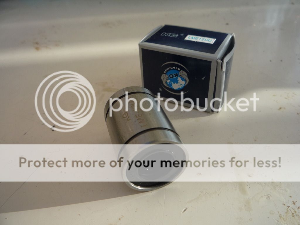
Update on bearings, just arrived:

fulcrumbearing.jpg
 
Yes:

LME European Metric Series Rubber Sealed Linear Ball Bushings: Manufactured with rubber seals these linear ball bushings are characterised by their smooth movement, high rigidity and low friction, they are easy to maintain or replace and have a good life span in service. They consist of steel outer housings with sets of balls running around their own tracks within the low friction polyamide / steel inner raceways. The UU series has the benefit of rubber seals to prevent the ingress of dust and moisture.
Closed: LM Closed types - the outer raceway is solid with no relief machined so clearances are preset, choose the adjustable type if you need to control clearances. LME types differ from the LM types only in sizes
Benefits: Low friction, low maintenance, rubber seal limits moisture and dirt ingress, cost effective solution
 
Day 30

Cut off existing damper mountings from vertical links and sprayed with primer prior to the blue topcoat. In between coats did a little more lightening to rear ARB support brackets, removing 12gms from each. I know, I know :)

reararbfinallightening.jpg
 
Last edited:
I knew that :) (but others may not)

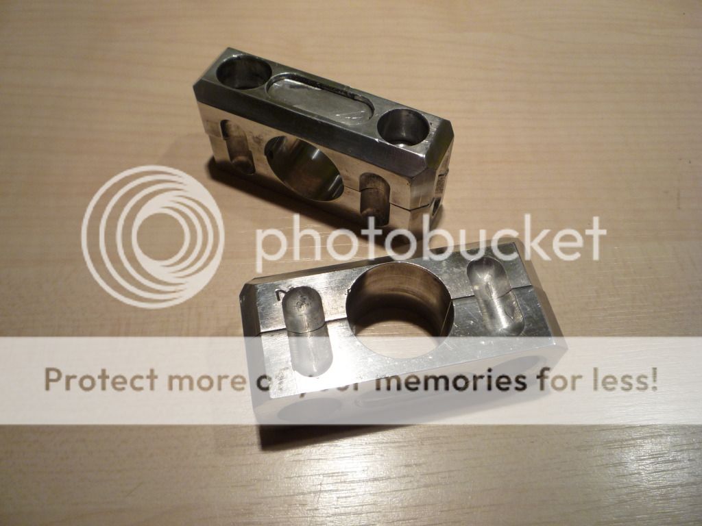
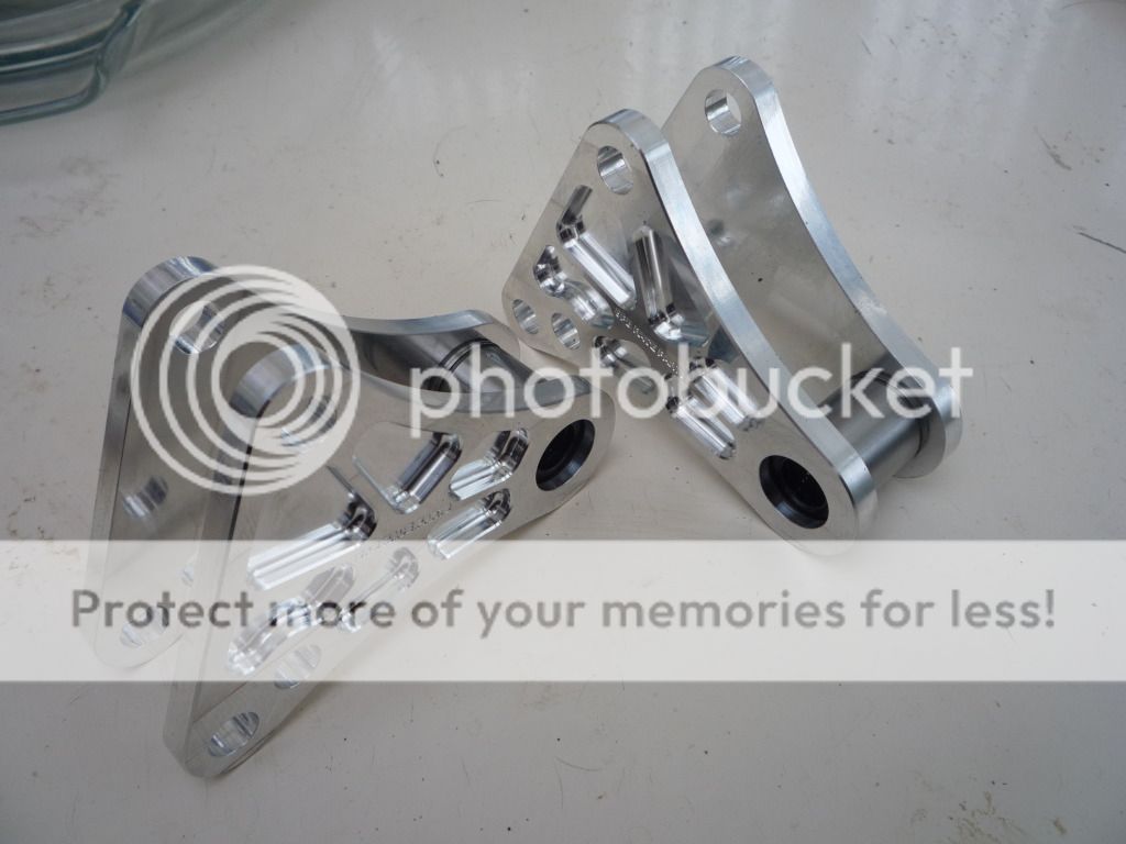
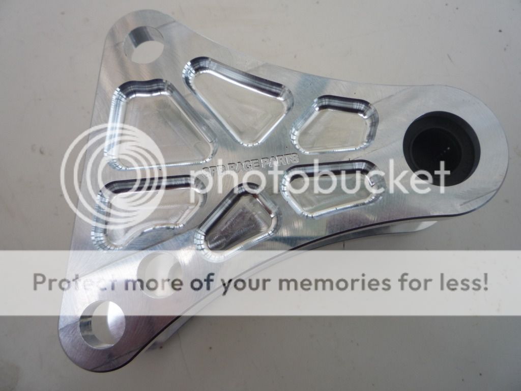
The fulcrum for the inboard dampers. They serve as both bearing and connector between the two halves of the fulcrum.
 
Day 31

Bit of a step back today. Sprayed the rear vertical links and had a reaction with the blue paint going all crinkly (even with a primer). Decided to blast back to metal and start again but my blaster isn't man enough to remove the powder coat under the paint so it is off to a local powdercoater who has a proper blaster. I will probably get him to paint them as well.

P1020315_zps90c73404.jpg
 
Last edited:
Day 32

Price to blast and powdercoat in blue around £100. He said an option would be to soak in nitromors and pressure wash, so I am going to try that as it will be the cheaper option if it works. They are soaking in a bath of the stuff as I type.

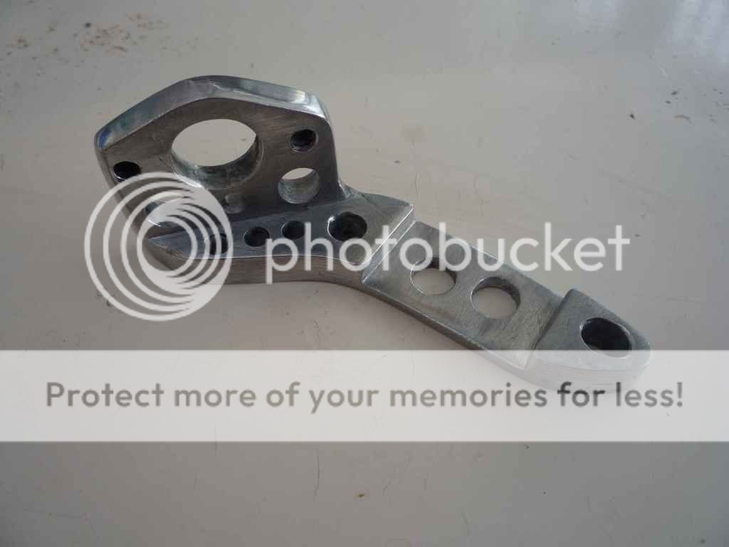
12gms removed from crank sensor bracket (just over 25%)

cranksensorbracketlightened_zps68ada1d8.jpg
 
I hold my hand up as to one of those who had no idea what it was :embarrest:

Mainly used in engineering, I have specified them in various automation equipment and robotic applications. Normally used with hardened and ground shafts for linear movement.
 
Day 33:

Continued to strip vertical links of paint and powdercoating.

Day 34.

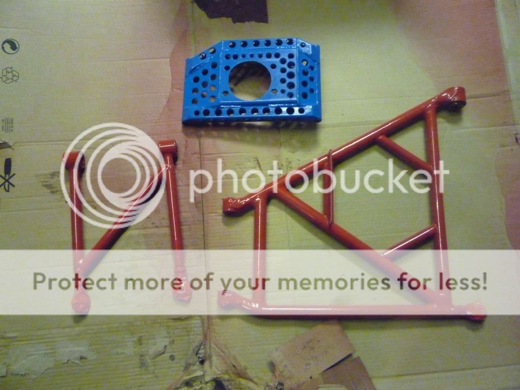
Finished stripping and they are now painted, along with wishbone. I still prefer them black but needs must:

rearsuspensionpaintedredandblue_zpsfbc9cbaa.jpg


Picked up fulcrums today and pressed the bearings into place:

fulcrumsfinished1_zps9c79a352.jpg

fulcrumsfinished_zpsa38c3e1c.jpg
 
That's a relief :) This material is used for highly stressed components, such as, as mentioned on one site, Trusses, Bridges, Cranes, Transport applications, Ore Skips, Beer Barrels, Milk churns :)

This, apparently, is commonly used for racing car parts. What would you use, I assume 2014A? I am looking to replace my steel vetial links with alloy ones of my own design, so a headsup on a suitable material would be much appreciated.
 
6082-T6 is more known as a general use alloy, used in forged production parts of suspension arms etc. I use it for all general engineering applications. As said it is used across alot of other areas but for highly stressed components 2014A or similar spec is used in aerospace etc. This I have specified where a particular part or assembly is subject to excessive conditions or repetitive actions where fatigue is the issue. Besides 6082 is cheaper than 2014 or equivalent.

For high end use the 3D modelling designs can be assessed using FEA.
 
I think that that would be the material to use for the uprights, then.

With regard toFE, FeatureCam has a stress analysing facility, but have no idea yet how to use it or if it is any good.

I think I will have to rely on my common sense (oh dear) and Graham Hatherway's experience.

The existing steel uprights weigh 4.5kg each, even with all of the holes, so I would hope to reduce that to less than 3.5Kg - possible?
 
When in Inventor, specify the material type for your design and in iproperties update the materials mass and then do it again in say mild steel and again in aluminium then compare.
 
Day 35

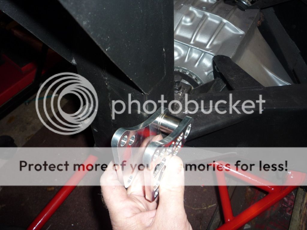
Looked at how to mount rear dampers. Initially the plan was to make a full width barcket assembly to mount both the dampers and fulcrums to. However, on looking at it again today, I thought that I could mount the fulcrums onto the existing suspension turrets (now only used to support the body and mount roll bar and belts to):

reararbdesignthoughts_zps265c4612.jpg


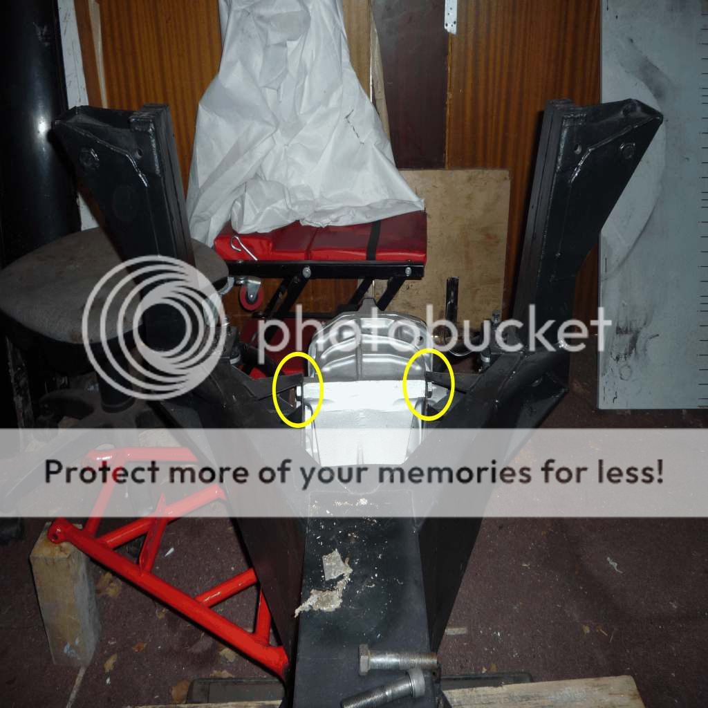
Then I had a eureka moment. I spied the diff mounting bolts (circled in photo below) and thought why not use these to secure the damper bracket to? This would result in the bracket being a third as long/heavy and use existing bolts (if possible make one bolt do more than one job). A quick trip to Graham Hatherway's and my ideas were found to be valid, so quickly back home to mock up a pattern and then back to my fabricator (Graham's son-in-law) to get it made (hopefully by the end of the week. I thought about fitting the bracket directly to the diff housing by drilling and tapping, but there may be heat soak issues and I don't want hot dampers.

reararbdesignthoughts1withboltscircled_zps2a530041.jpg
 
Last edited:
Day 36

Stuff ordered today for inboard damper assembly:

McGill Motorsports
7/16UNF rod ends RHT x2
M10 rod ends LHT x2
Plus half nuts

Trident Racing Supplies
7/16UNF x3" x2 caphead bolts
M12 x 160 x4 caphead bolts
M10 x 50 x4 caphead bolts
M10 x 55 x4 caphead bolts

Simply Bearings
12 x 26 x 4mm needle roller thrust washers x4
 
Day 36 update

Just received an email from XoomSpeed to say the full throttle gear change magic box is made, so I will be arranging payment very shortly.
 
Is that a form of powershift that retains peak power and torque during up shifts? I was working on something similar back in the early 90s.
 
Near on identical, we also had a learn function for race tracks. Great piece of kit by the looks of it. I had all the parts once upon-a-time for a pneumatic shifter only to be informed the car I was building was deemed illegal by the clubs technical committee, same people that were running in the same class :sad2:
 
:lol: If and when you create an assembly with components and fixings you can then create an idw file, one with a border. From this you create the projected 2D views, dimensions and bill of materials (BOM) etc.
 
Ah, BOM. I am used to BOQ from my working days.

Just ordered a How To book from Amazon, so soon be back to school.
 
Day 37

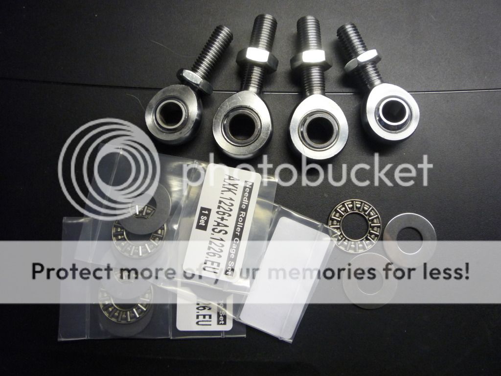
Rod ends and needle roller bearings arrived today:

reardamperconnectingrodrodends_zps48a6eb4e.jpg


I forgot that I need threaded sleeves that will be welded into the connecting rods that these rod ends will be fitted to. Ooops, off to order now.
 

Similar threads


Please watch this on my YouTube channel & Subscribe.


Back
Top